
 English
 Français
 Español
 Árabe
 Deutsch
 简体中文
 Português
 Русский
 日本語
 한국어
 हिंदी
 Prancis
 Türkçe
 Tiếng Việt
 Italiano
 ไทย

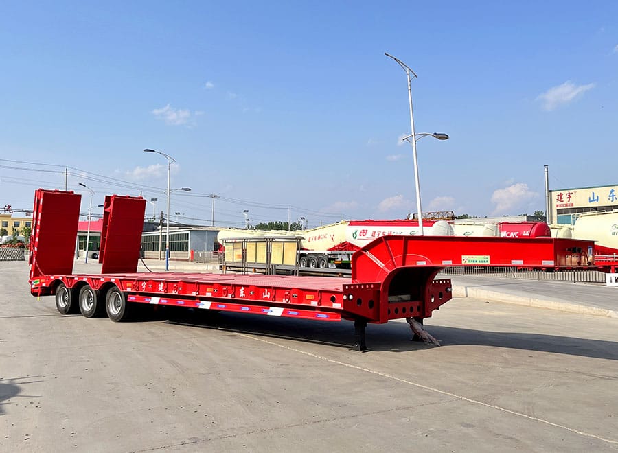
A wheel loader can fit within the outline of a low bed deck and still be a poor match for the trailer. Its tires may sit near an unsupported edge, the bucket may conflict with the gooseneck, or an underside component may approach the ramp transition before the machine reaches its final position.
The useful question is not simply whether the trailer is long and strong enough. It is whether the complete machine, in its agreed transport configuration, can be loaded, supported and secured using a documented arrangement. The following checks help turn that question into a clear enquiry.
Use the exact machine and attachment combination
Give the trailer supplier the wheel loader’s model, serial-number range and current configuration. Include the bucket or other attachment, tire specification, counterweights and relevant optional equipment. A model name alone may cover configurations with different mass and dimensions.
Separate operating dimensions from transport dimensions. Bucket position, attachment choice and optional equipment can affect the envelope presented to the carrier. Where manufacturer data contains assumptions, keep those assumptions with the dimensions rather than copying a single number into a quotation.
Caterpillar’s published wheel-loader information illustrates why configuration notes matter: its dimensional and weight tables identify particular arrangements. Those figures are examples for the listed Cat equipment, not a specification for every loader and not evidence that a GENRON trailer can carry one. Use the documentation for the actual machine being transported.
Further source information:
Map the tire footprints onto usable deck support
Record wheelbase, tire width, outside width over tires and the position of each contact area. Then overlay those dimensions on the proposed deck drawing. Ask the designer to distinguish the overall deck width from the portions intended to support the machine’s wheels.
A wide overall machine dimension does not explain whether each tire is properly supported. Likewise, a narrow central deck may appear adequate in a side view while a plan view reveals a mismatch. Both views belong in the discussion, especially where extensions or tapered deck sections are proposed.
Identify tire positions relative to structural members and any changes in floor construction. The relevant review concerns the actual wheel loads and their locations, not an assumption that the machine’s total mass is evenly spread over the full deck. Ask which load cases the supplier has considered.
Wheel-loader information for a low bed drawing review
| Machine detail | Why it belongs on the drawing |
|---|---|
| Transport mass and configuration | Defines the machine and attachments included in the load case |
| Wheelbase and tire footprints | Shows where concentrated wheel loads reach the deck |
| Bucket width and travel position | Identifies front overhang, clearance and separate support questions |
| Lowest underside points | Allows the loading-path transitions to be checked |
| Transport height | Supports the loaded-height and route review |
| Manufacturer securing provisions | Helps the planner match machine and trailer attachment access |
Check the journey onto the deck, not only the parked position
Request a side-view assessment of the loading path. It should show the ramp, the transition onto the main deck and any step or gooseneck feature the machine approaches. A final-position drawing does not reveal every clearance encountered during loading.
Provide the machine’s underside profile and relevant clearance information. Wheelbase, tire geometry and overhang all influence how a wheeled machine passes a change in slope. There is no single ramp angle that can be declared suitable for every loader from its weight alone.
The loading-path discussion should also cover the loads imposed on the ramps and trailer during the transition. Ask what loading conditions and site assumptions apply. The manufacturer’s instructions and a competent loading plan should determine the actual method; this guide is not a drive-on procedure.
Decide what travels attached and what travels separately
If the bucket remains attached, define its agreed transport position and the space it occupies. If it is removed, record its mass, dimensions, support needs and separate securing provisions. Removing an attachment may reduce one dimension while creating another cargo-handling task.
Include spare buckets, forks, quick-coupler equipment and loose accessories in the load schedule. Do not let these disappear from the quotation merely because the main loader fits. They consume payload and deck space, and they need an approved way to be loaded and restrained.
For articulated machines, obtain the relevant manufacturer instructions concerning transport and any articulation-locking provisions. Do not infer suitable practices from a different model or assume that steering components can be used as tie-down points. The trailer’s fittings should allow access to the securing arrangement chosen for that machine.
Separate low deck height from overall route clearance
A lower deck can help reduce transport height, but the route review needs the complete loaded combination. Start from the agreed deck condition and machine transport height, then confirm the assembled envelope. Tire, suspension and operating-condition assumptions should be consistent between the drawing and the actual move.
Discuss width, height, overhang and route constraints with the transport operator before finalising the order. A heavy-duty trailer is not automatically authorised for any public road, and an equipment fit drawing is not a movement permit.
Do not trade away necessary wheel support simply to reduce a headline height or width. If the proposed arrangement conflicts with the route, the answer may involve a different trailer layout, a revised machine configuration or a different movement plan. That decision needs the responsible parties, not a sales-page comparison alone.
Compare two quotations on the same transport sketch
An illustrative enquiry might include one loader with its normal bucket attached and a second case with the bucket carried separately. Ask both suppliers to quote against those same two cases. Their responses should identify deck length, support areas, ramp arrangement and any exclusions for each case.
A quotation that addresses only the easier configuration should not be compared as though it covers both. Put the missing review items in an exception list. This makes the difference visible before price negotiations, when changes to deck geometry or supplied fittings are still easier to discuss.
At handover, compare the delivered deck and ramp arrangement with the accepted drawing. Retain the machine data and drawing revision together. If a fleet later substitutes another loader, repeat the fit and loading-path checks rather than assuming a similar model name means an identical transport requirement.
Wheel-loader transport brief
Machine make, model and configuration reference:
Transport mass, including attachments and accessories:
Wheelbase, tire widths and outside width:
Transport length, height and underside-clearance drawing:
Bucket attached or carried separately:
Required deck support and manufacturer securing information:
Tractor, loading site and unloading site:
Route envelope and responsible transport planner:
A useful fit-review meeting has three drawings
Bring a plan view, a side view and the machine’s transport-configuration record to the review. The plan view answers where the tires and attachment sit. The side view addresses length, height and the loading path. The configuration record establishes which machine, tires and attachments those views actually represent.
Use a short issue list beside the drawings. An unresolved tire-support question, an unknown underside dimension and an unconfirmed bucket position are different issues with different owners. Assign each one to the party able to supply the evidence, and do not mark the complete arrangement accepted while an essential item remains open.
This method also helps a buyer compare alternatives. A longer deck may answer the space question without answering wheel support; a lower deck may change the loading transition. Keeping the three views together makes those trade-offs visible and reduces the chance of selecting a trailer from one favourable dimension in isolation.
Wheel-loader transport questions
Is operating weight sufficient for a trailer quotation?
It is a starting point, not the complete input. The supplier also needs the machine configuration, dimensions, tire positions and attachment schedule. Confirm what the stated weight includes.
Can deck extensions support part of a tire?
Only if the specific extension arrangement is designed and accepted for that duty. Do not assume that an extension’s visible width establishes its load-bearing capability. Obtain the applicable drawing and restrictions.
Does a longer ramp guarantee underside clearance?
No. Clearance depends on the complete machine geometry and the transitions along the loading path. Ask for a machine-specific review instead of choosing ramps from length alone.
Can one low bed serve several loader models?
It may, if each required configuration is included in the reviewed load envelope. Give the supplier a fleet matrix and identify the largest, heaviest and most clearance-sensitive cases, which may not be the same machine.
Related Reading
Sources and Scope
Manufacturer examples are model-specific. DVSA guidance applies in Great Britain; destination requirements must be checked separately. This enquiry guide does not approve a loader, ramp, restraint arrangement or route.


