
 English
 Français
 Español
 Árabe
 Deutsch
 简体中文
 Português
 Русский
 日本語
 한국어
 हिंदी
 Prancis
 Türkçe
 Tiếng Việt
 Italiano
 ไทย

Two agricultural tractors with the same model designation may arrive for transport in very different forms. One may have narrow tires and no front ballast. Another may carry wheel weights, a front loader, dual wheels or an attached implement. Treating them as the same load can leave both dimensions and mass poorly defined.
A good enquiry does not require the buyer to design a trailer. It requires a clear inventory of the tractor and everything travelling with it. This guide shows how to prepare that inventory and where to ask for a drawing review before agreeing on a low bed configuration.
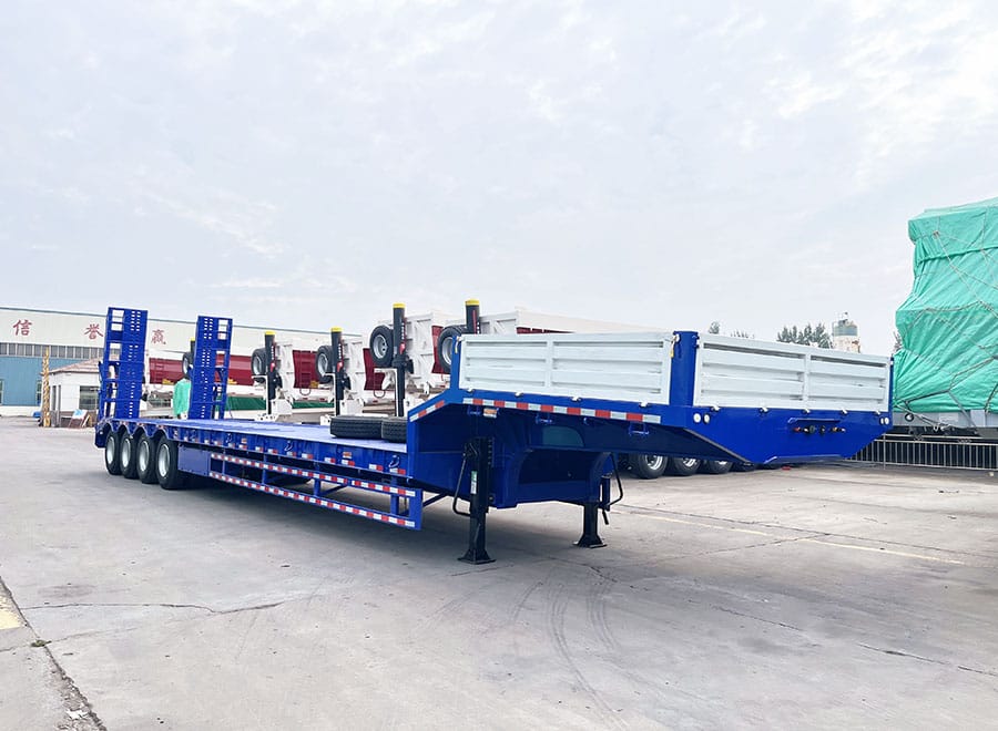
Build a transport inventory before comparing payload figures
Start with the tractor’s make, model and identification details, then list the equipment fitted to that particular unit. Include front and rear ballast, wheel weights, a loader, brackets, front linkage and other substantial additions. Record the evidence used for mass, whether it is an appropriate weighing record or configuration-specific manufacturer information.
Identify tire ballast if present and establish whether it is included in the stated mass. Do not copy a brochure figure without checking its assumptions. A number described as a base, shipping or operating weight may represent a different configuration from the tractor waiting in the yard.
Create a separate line for each implement and loose component travelling on the trailer. A mower, plough, bucket or removed wheel is not an incidental item when it occupies deck space or needs handling equipment. Recording it separately prevents it from being overlooked during payload, support and restraint planning.
Measure the tire arrangement that will be transported
Record the outside width over tires, individual tire widths, wheelbase and wheel contact positions. If dual wheels or an adjustable track setting are involved, state the agreed transport configuration. Do not assume they will be changed simply because a narrower arrangement appears in a catalogue.
Any adjustment or removal should follow the tractor manufacturer’s instructions and be carried out by the responsible personnel. The quotation should identify the configuration it assumes, not quietly depend on unagreed workshop work at the loading point.
On the trailer drawing, distinguish nominal deck width from the supporting surface beneath each tire. Show where the front and rear wheels land. A configuration with widely spaced rear tires and narrower front tires may require more thought than one overall width dimension suggests.
Keep these tractor and cargo descriptions separate
| Description | Information to establish | Why it changes the enquiry |
|---|---|---|
| Base tractor | Model and the assumptions behind published mass | Prevents a bare-machine figure being used for a fitted unit |
| Ballast and options | What remains fitted during transport | Changes the actual mass and possibly its distribution |
| Tires and track setting | Width, duals and wheel positions | Defines the required supporting footprint |
| Attached implement | Travel position and complete envelope | May govern length, width or underside clearance |
| Separate cargo | Mass, footprint and handling method for each item | Requires its own space, support and restraint provision |
Decide whether implements travel attached or separately
An attached implement may make a convenient yard combination but an awkward transport load. Its position can extend beyond the tractor or occupy space above the gooseneck. Obtain the manufacturer’s transport instructions and have the proposed arrangement assessed rather than assuming a road-travel position is also suitable on a carrier.
If an implement is detached, show where it will sit and how it will be handled. Its transport supports may differ from the points used while working. Include any stands, frames or protective pieces that are required to keep it stable and avoid damage.
The choice is not simply attached versus detached. It is a comparison between two complete cargo arrangements. One may need a different loading sequence; the other may require additional lifting equipment and separate restraint. Put those consequences beside the trailer price when deciding which arrangement is practical.
Review the loading path with the tractor’s low points visible
A tractor’s tire size does not by itself establish that it will clear a ramp transition. Provide a side view showing low components, overhangs and the agreed attachment position. Front weights, a loader assembly or a mounted implement may affect the loading envelope.
Ask which ramp and deck load cases the trailer proposal covers. Where multiple tractors will use the vehicle, identify the different wheelbases and tire footprints. The heaviest tractor may not be the one with the most difficult transition clearance.
Loading and unloading sites also matter. Describe the available area, surface condition and handling equipment to the transport planner. A suitable vehicle specification should be paired with a safe operating plan; no generic drive-on instruction in a buying article can replace that site-specific work.
Use the tractor manual for transport-specific provisions
Obtain the operator’s manual for the actual tractor and relevant implements. John Deere’s official manual resources, for example, direct owners to equipment-specific instructions rather than one universal procedure. The correct manual is the appropriate starting point for identifying transport and securing provisions on that machine.
Give the load-securing planner access to those instructions and the trailer drawing. Ask that the selected attachment points remain accessible once the tractor and separate implements are in their final positions. A tie-down point hidden behind another item is not useful simply because it exists.
Do not use hydraulic hoses, steering parts or convenient bodywork as assumed attachment points. Where the documentation is unclear, resolve the issue with the equipment manufacturer or responsible specialist before transport. The trailer enquiry should expose this missing information rather than conceal it with a generic chain illustration.
Further source information:
Compare a fleet of tractors with a configuration matrix
For a dealer or agricultural contractor, prepare one row per transport configuration rather than one row per model. A tractor alone, the same tractor with a loader, and the tractor plus a separate implement may need three rows. Include mass, envelope, wheel positions and unloading requirements for each.
Mark whether the proposed low bed covers each row, requires a documented changeover or excludes it. This is more useful than a broad statement that the trailer is suitable for agricultural machinery. It also shows when a single compromised layout would be less practical than separate transport arrangements.
At handover, retain the accepted matrix with the drawings and equipment list. If the fleet adds larger tires, extra ballast or a new implement, revisit the affected row. A manageable update process helps prevent an originally well-defined order from becoming an undefined collection of loads over time.
Farm-tractor enquiry worksheet
Tractor make, model and configuration evidence:
Mass as transported and what that mass includes:
Front/rear ballast and fitted options:
Tire sizes, outside width, dual wheels and wheelbase:
Attached implements and their agreed transport positions:
Separate implements, supports and loose accessories:
Complete load dimensions and loading-site information:
Manufacturer manuals and responsible transport planner:
Give a dealer consignment an item-by-item loading list
For a hypothetical dealer delivery, list the tractor, a detached front bucket and a rear implement as three cargo items. Give each a mass, footprint, support description and handling reference. Then show the complete arrangement on one drawing. This prevents the accessory list from becoming a second, unplanned load after the tractor position has already been agreed.
If several tractors travel together, repeat the exercise for each unit rather than multiplying the dimensions of one machine. Different tire settings or fitted options can change how the available deck is used. The transport planner should also review the conditions after any intermediate delivery.
At collection, compare the actual equipment with the loading list. A substituted implement or additional ballast is a change to the stated cargo, even if the tractor model is unchanged. Establish who can authorise that change and what needs rechecking, so the driver is not left to resolve a procurement assumption at the yard gate.
Agricultural tractor transport questions
Can I quote from the tractor’s horsepower?
No. Power does not define transport mass, wheel footprint or overall dimensions. Use the actual tractor configuration and its equipment schedule.
Should ballast always be removed before transport?
There is no universal answer. Follow the tractor manufacturer’s requirements and the reviewed transport plan. If removal is proposed, define who performs it and how the removed ballast will travel.
Are deck extensions automatically suitable for dual wheels?
No. The supporting arrangement must be designed and reviewed for the actual wheel positions and loads. Visible deck width is not a substitute for that assessment.
Can the attached implement be ignored if it is light?
No. Even a relatively light implement can change the transport envelope, loading clearance or securing access. Include it in the cargo schedule so those effects are considered.
Related Reading
Sources and Scope
This is a procurement and configuration-recording guide, not a tractor operating procedure or movement approval. Manufacturer instructions are equipment-specific, and DVSA guidance is jurisdiction-specific.


