
 English
 Français
 Español
 Árabe
 Deutsch
 简体中文
 Português
 Русский
 日本語
 한국어
 हिंदी
 Prancis
 Türkçe
 Tiếng Việt
 Italiano
 ไทย

A road roller is not simply a small excavator with a different shape. Its drums, tires, articulation and low components create a different set of questions for the carrier. A trailer that provides ample overall space may still leave an important support or loading-path detail unresolved.
For a paving contractor or equipment dealer, the requirement is often a fleet rather than one machine. A compact tandem roller, a combination roller and a larger soil compactor may all need transport. The most useful enquiry explains those configurations separately and shows which journeys require more than one item on the deck.
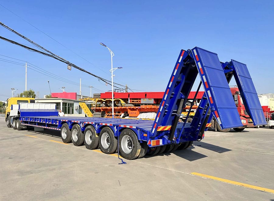
Identify the roller configuration before quoting its weight
Record the make, model and relevant identification of the roller, then describe its actual arrangement: tandem drums, a drum with pneumatic tires, or another configuration. Include the cab or protective structure, fitted options and equipment that remains attached during transport. A family name can cover more than one build.
Keep the source of the mass figure with the enquiry. Manufacturer data may distinguish standard and maximum operating configurations, and the conditions behind those figures matter. Ask the equipment owner to establish the transport mass rather than treating whichever brochure number is easiest to find as a verified vehicle load.
Caterpillar’s CB8 specifications, for example, list different operating-weight entries associated with configuration. That illustrates why the equipment description should travel with the number. It is not a capacity recommendation for a GENRON trailer, and the CB8 values should not be copied to a different roller. Use the actual machine record.
Source: Caterpillar: CB8 compactor specifications and configuration entries
Draw the drum and tire contact areas on the deck
Provide drum widths, outside machine width, wheelbase and the locations of the supporting contacts. For a combination roller, include the tire arrangement as well as the front drum. The trailer designer needs to know where the load enters the structure, not merely the outline of the machine when viewed from above.
Distinguish compaction width from overall transport width. Handrails, mirrors, cutters or other fitted parts may extend beyond the working drum. Conversely, the widest visible part does not define the load-bearing footprint. Keeping those dimensions separate prevents a support assessment from being based on an unrelated catalogue measurement.
Ask for the intended parking position to be marked on the trailer plan. If deck extensions are proposed, their function and permitted loading must be explicit. An extension that fills a gap visually should not be assumed capable of supporting any part of a roller. The relevant support arrangement needs the manufacturer’s review.
Assess ramp transitions as a continuous loading path
A side-view drawing should show the route from the loading surface, along the ramps and onto the main deck. Include the roller’s underside profile, overhangs and other low points. The final parked position can look generous while a transition along the way remains the limiting feature.
Avoid selecting a ramp from a generic angle or length rule. The machine geometry, trailer arrangement and assumed site condition must be considered together. Ask the trailer and equipment specialists to identify the loading cases covered by the proposal and any restrictions that the operator will need to follow.
This is also where the ramp’s supporting duty should be made clear. Total trailer payload does not establish a ramp rating or define the loads present while a machine crosses from one support to another. Obtain the appropriate manufacturer information and a competent loading plan; do not substitute an improvised drive-on demonstration for that review.
Road-roller information that belongs in the enquiry
| Input | What to provide | What it helps resolve |
|---|---|---|
| Machine identity | Exact model, build and fitted equipment | Which transport configuration the proposal covers |
| Contact geometry | Drums, tires, widths and wheelbase | Deck and ramp support positions |
| Underside profile | Low points and front/rear overhangs | Clearance along the complete loading path |
| Transport envelope | Length, width and height with options | Deck fit and route review |
| Additional cargo | Second machine, tools and accessories | Combined mass, layout and restraint access |
Compare usable layout rather than a headline deck size
Measure the usable supporting area on the proposed drawing. A gooseneck transition, rear structure, fixed fittings or a change in deck construction can affect where the roller may sit. Overall vehicle length and maximum platform width are not a complete description of usable machinery space.
For a single-roller enquiry, the three-axle machinery low bed layout is one product layout to discuss with GENRON. Where the load envelope differs, the low bed platform with a different deck arrangement provides another starting point for comparing geometry. Neither link confirms that a particular roller is accepted; the drawing review should identify the actual configuration and any changes required.
Keep the comparison practical. If one proposal needs removable equipment to create the intended space, include its handling and stowage in the scope. If another offers a simpler permanent layout but less flexibility, record that trade-off. The better choice is the one that covers the agreed work clearly, not automatically the largest platform.
Include water, attachments and loose items in the cargo record
Ask the equipment owner what condition the roller will be in when presented for transport, including relevant tanks and fitted accessories. The transport record should explain what is included in the stated mass. This article does not prescribe draining, filling or altering a machine; the manufacturer’s requirements and responsible operating plan determine its preparation.
List loose items separately. Small plates, tools, spare components and other equipment can occupy working space or obstruct a selected attachment point even when their mass is modest. Their storage location and restraint should be part of the load arrangement rather than an afterthought beside the roller.
The same discipline helps when a driver collects a substitute machine. A roller with an extra fitted attachment is not automatically equivalent to the one on the accepted drawing. Establish who checks the equipment against the transport list and who resolves differences before the vehicle is assigned to the move.
Plan multi-machine loads as a separate operating case
A paving fleet may want to carry two rollers or combine a roller with another item of plant. Draw that arrangement explicitly. Add the actual masses and accessories, show every support footprint and identify the space required for the selected securing equipment. Passing a total-mass check is only the first screening step.
A useful hypothetical brief has Case A for one large roller and Case B for two compact machines. Ask the supplier to identify whether both cases are covered, whether the same fittings are used and what restrictions apply. Do not assume that a trailer accepted for one central machine has been assessed for two machines in different deck positions.
If machines are delivered to separate sites, include the intermediate condition after the first delivery. Remaining equipment still needs suitable support and restraint, and removable ramps or fittings must remain organised. The delivery order should be agreed with the transport planner rather than chosen solely for convenient access at the first customer.
Keep machine provisions separate from trailer anchor points
Obtain the roller manufacturer’s transport and securing information for the actual model. Give it to the competent load-securing planner alongside the trailer drawing. The planner can then check whether the chosen machine provisions and vehicle attachment points remain accessible in the proposed position.
Do not infer a suitable tie-down location from a handrail, articulation component or convenient opening in the bodywork. Likewise, a robust-looking trailer fitting does not establish its rating. The order should identify the supplied attachment provisions and the documents used to define the load-specific arrangement.
At handover, check that the relevant fittings and labels match the accepted drawing. If the layout changes during manufacture, update the loading and restraint documents before relying on them. Clear records are particularly useful when equipment is hired or drivers change, because the original quotation discussion may not be available to the person making the journey.
Review the destination as carefully as the collection yard
A factory or rental depot may offer a broad loading area while the paving site has limited access. Record the collection and delivery locations, available working area and the parties responsible for managing vehicle movements. The transport specification should not depend on site facilities that have not been confirmed.
Send the complete loaded envelope to the route planner, including the agreed machine configuration. A lower deck can help with overall height, but it does not establish road access or clearance on its own. Applicable limits and any required movement arrangements need to be confirmed for the actual journey.
Use photographs to explain the sites and machinery, but retain dimensional and responsibility records as well. A photograph cannot show every obstruction or prove a safe loading area. If a destination changes, review the affected conditions rather than treating the first successful delivery as approval for every future job.
Create a fleet-fit register that can be updated
Give each accepted machine configuration a reference tied to the trailer drawing revision. Record its transport mass basis, contact geometry, accessories and load arrangement. Mark whether the configuration is covered, covered with stated conditions or still awaiting review. That makes the quotation outcome usable by dispatch staff.
When a new roller enters the fleet, compare its record with the accepted envelope instead of judging from a similar appearance. The review may be straightforward if the relevant features match, but the decision should still be made by the responsible parties. Small dimensional differences can matter when clearances or support positions are already tight.
This register also improves the next purchase. It shows which machines drive the trailer requirement and which optional features are rarely used. A buyer can then request a defined upgrade or a more focused layout, rather than repeating a broad request for a heavy-duty low bed without evidence of the actual fleet needs.
Road-roller transport brief
Machine model and configuration reference:
Transport mass and included equipment:
Drum/tire footprints, wheelbase and outside width:
Transport envelope and underside profile:
Single-machine and multi-machine cases:
Loose equipment and storage requirements:
Loading, route and receiving-site responsibilities:
Required drawings, instructions and acceptance records:
A quotation comparison should expose its exceptions
Put the two or three proposed trailer layouts beside the same machine matrix. For each machine, ask whether the offer covers its support footprint, transition clearance and required accessories. Mark a clear answer rather than accepting one general statement that the vehicle carries road-construction equipment.
Suppose one proposal covers a tandem roller but excludes the contractor’s combination roller because a needed dimension is missing. That offer is not necessarily unsuitable, but the missing review must remain visible. Name the party supplying the dimension and the decision needed before the order can be accepted for both machines.
Keep cost and timing consequences with the exception. A change to ramp geometry or removable fittings may affect delivery, equipment scope or routine preparation work. When these items are resolved on the same comparison sheet, the final price has a defined meaning. When they remain scattered through messages, a seemingly complete quotation can still leave the fleet without an agreed arrangement for part of its work.
FAQ: Low bed trailers for road rollers
Can I select a trailer from the roller’s operating weight alone?
No. Establish the actual transport configuration, then include drum or tire geometry, wheelbase, underside clearance and attachments. Operating weight is useful only with its stated assumptions. The complete loading and support arrangement still needs review, even where the total mass is comfortably below a quoted trailer payload.
Is compaction width the same as transport width?
Not necessarily. Compaction width describes the working area, while mirrors, protective structures or fitted equipment may determine the overall transport envelope. Give the supplier both the support-contact dimensions and the maximum outside dimensions. They answer different questions on the drawing.
Can a roller drum run partly on a deck extension?
Only where the specific supporting arrangement is designed and accepted for that duty. Do not infer capacity from the visible extension width. Ask for the permitted machine position and applicable restrictions to be identified by the responsible manufacturer or specialist.
Does a longer ramp always solve a clearance problem?
No. The complete transition geometry and machine profile need assessment. A longer ramp can change the approach, but another transition or low component may still govern the loading path. Use a machine-specific drawing review rather than a universal ramp-length rule.
Can one low bed carry two compact rollers?
Potentially, but treat that as its own load case. Show both machines, accessories, support positions and securing access, and include any intermediate condition on a multi-stop route. Acceptance of a single-machine arrangement does not establish acceptance of every combined load.
What should be ready before the first collection?
The actual machine list, accepted trailer and load drawings, relevant manufacturer instructions, responsible loading and securing arrangements, and route/site information should be consistent. Resolve substitutions or missing dimensions before relying on an old quotation. The aim is a repeatable transport arrangement, not merely a matching model name.
Product Options to Discuss
Product pages are starting points for a configuration discussion. Confirm machine-specific support, ramps, ratings and route suitability in the accepted proposal.
Related Reading
References
Manufacturer data is model-specific. This guide supports procurement and load-case definition; it is not a loading procedure, restraint calculation or route approval.


